Wiki Receiver and transmitter
Receiver
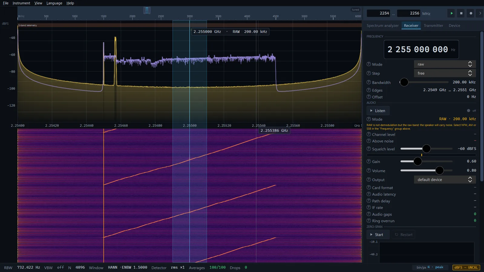
The receiver turns the band marked on the spectrum into audio. The frequency, mode and filter width are set by the VFO — the same band you see on the plot — while the Audio group switches listening on, holds the squelch and shows in numbers why a station sounds good or bad.
Getting audio
- Open the Receiver tab in the side panel. It holds three groups: Frequency, Audio and Zero-span (the last one is covered in Zero span and trigger).
- Left-click a signal on the spectrum or the waterfall — the VFO moves to that frequency.
- In the Frequency group choose the Mode. After start-up it is
raw— the raw band without demodulation, which gives noise in the speaker. - Press Listen. The button changes to Turn off, and the squelch state appears on the right: squelch open or squelch closed.
- Adjust Squelch level, Gain and Volume.
After the app starts, listening is off and the mode is raw with a 200 kHz bandwidth. Volume, squelch level, audio gain and the output device are saved on exit and restored next time; the VFO mode and bandwidth are not.
The VFO: where the receiver listens
The device captures a band as wide as its sample rate. The VFO is the point inside that band where the receiver sits. It moves only within what is already captured and does not retune the device: the spectrum does not blink and the waterfall history stays intact. To listen outside the captured band, move the band itself first (see The main window and controls).
On the plot the VFO is a translucent band across the full height of the spectrum and waterfall, a vertical line at the tuned frequency and a label with the frequency, mode and filter width. The band is light blue while it fits into the capture and red when it has gone past its edge.
- Left click on the spectrum or waterfall — the VFO moves to the frequency under the cursor.
- Drag the band by its body — the VFO follows the mouse. Drag the band itself: dragging across free space on the plot selects a range for measurement.
- Drag an edge of the band — changes the filter width. In symmetric modes the centre stays put and the band widens on both sides. In USB the lower edge is the tuned frequency itself, so it retunes the receiver while the upper edge changes the width; in LSB it is the other way round.
- The dial in the Frequency group: hover over a digit and turn the mouse wheel, or click the upper or lower half of the digit — that digit alone changes.
- Double-click on the spectrum shows the whole band; the VFO stays where the first click put it 0.9.42.
- Ctrl+drag with the left button — over the VFO band too — moves the view, not the VFO 0.9.42.
PRO In SDR SA PRO the receiver can be tuned in two more ways. In the Scanner list, a right-click on a row → Tune the receiver to the signal puts the receive band centred on the signal and the VFO on the signal with the width of the row; in a sweep this stops the sweep (see Scanner). The Receiver → to marker button in the trace markers group puts the receiver centre on the selected marker (see Trace markers).
The Frequency group
This group appears on the Spectrum analyzer, Receiver and Transmitter tabs, and everywhere it is the same VFO.
- Mode
- The list of modes, written in lower case:
raw,nfm,wfm,am,dsb,usb,lsb,cw,fpv-video. Changing the mode immediately sets its default bandwidth. - Step
- The grid the VFO frequency is rounded to: free (no snapping, the default),
1 kHz,6.25 kHz,12.5 kHz,25 kHzor100 kHz. - Bandwidth
- The channel filter width. The slider limits depend on the mode (see the table below). A filter wider than the signal feeds extra noise to the demodulator; a narrower one cuts the signal. In
fpv-videomode the slider is disabled. - Edges
- The lower and upper edge of the filter in absolute frequencies. Read-only.
- Offset
- The VFO shift from the centre of the captured band. The number turns red when the VFO band has gone past the capture edge: there are no samples there, and that side of the band is not received. A hint below the field suggests moving the centre or narrowing the bandwidth.
Modes and bandwidths
| Mode | What it is | Default bandwidth | Bandwidth limits |
|---|---|---|---|
| RAW | raw band, no demodulation | 200 kHz | 1 kHz – 20 MHz |
| NFM | narrow-band FM | 12.5 kHz | 2.5–50 kHz |
| WFM | wide-band FM (broadcast), mono | 180 kHz | 60–400 kHz |
| AM | amplitude modulation | 10 kHz | 2–40 kHz |
| DSB | double sideband without carrier | 6 kHz | 1–20 kHz |
| USB | upper sideband | 2.7 kHz | 300 Hz – 6 kHz |
| LSB | lower sideband | 2.7 kHz | 300 Hz – 6 kHz |
| CW | telegraphy, 700 Hz tone | 500 Hz | 50 Hz – 3 kHz |
| FPV-video | analogue video, no audio | the whole captured band | not adjustable |
- NFM and WFM. A frequency discriminator with 50 µs de-emphasis; there is no switch for the time constant. WFM is mono only: the 19 kHz pilot tone and the stereo subcarrier are not decoded. The WFM audio band reaches 15 kHz.
- AM. An envelope detector; the constant carrier level is removed from the audio.
- DSB. Demodulated without carrier recovery: if the tuning is not exact, you hear a beat.
- USB and LSB. The tuned frequency sits on the edge of the band: the lower edge in USB and the upper edge in LSB. That is exactly how the band is drawn on the spectrum.
- CW. The carrier is moved to a 700 Hz tone; the pitch is not adjustable.
- RAW. The raw band goes to the speaker, and the panel warns about it with a yellow line.
- FPV-video. A picture instead of audio — see FPV video.
If the VFO stands in the FM broadcast band (87.5–108 MHz) and the mode is not WFM, the panel says so plainly: broadcast needs WFM with a bandwidth of about 180 kHz, and a narrower mode clips the deviation.
The Audio group
- Listen / Turn off
- Switches demodulation and audio on and off. The dot and the caption next to it show the state: off, squelch open (green) or squelch closed.
- Mode
- The current VFO mode and bandwidth. Read-only: they are changed in the Frequency group. In RAW mode the value is yellow.
- Channel level
- The power in the channel filter bandwidth, in dBFS. This is what the squelch level is compared against. Green means the squelch is open.
- Signal in filter
- The bandwidth the signal really occupies (90 % of the power) against the filter width, for example "39.00 kHz of 180.00 kHz". If the signal fills less than 80 % of the filter, the value turns yellow and a hint suggests a narrower bandwidth: the rest of the filter feeds the demodulator nothing but noise. This row and Signal offset are shown only while listening is on.
- Signal offset
- How far the centre of the signal is from the centre of the filter, high or low. If the offset exceeds 15 % of the filter width, a hint names the frequency to retune to.
- Above noise
- How far the signal in the channel is above the noise in the same bandwidth, in dB. Above 20 dB it is green, 12–20 yellow, below that red. Below roughly 12 dB FM crosses its threshold and gives noise instead of audio: this is a property of the modulation, and the cure is an antenna, more gain or a stronger station, not volume. It is an estimate from the noise floor on the spectrum, not a calibrated measurement.
- CTCSS
- The detected sub-tone of a radio — see below. The row is shown only while listening is on in NFM or WFM.
- Squelch level
- The squelch: from −120 to 0 dBFS, −60 dBFS by default. Audio passes when the channel level is not below the threshold. The level is measured in the channel after the filter, so a strong neighbour on another frequency does not open the squelch. After the signal drops, the squelch stays open for another 0.25 s so that it does not chatter between syllables. Below the slider there is a level bar with a tick at the threshold.
- Gain
- Audio gain after the demodulator: 0–2, 0.60 by default. Above one, a strong station may clip.
- Volume
- The output level into the sound card: 0–1, 0.80 by default. It does not affect measurements.
- Output
- The audio output device: the system's default device or one from the list.
- Card format
- What was agreed with the sound card: sample rate, channels, bit depth. The receiver asks for mono 48 kHz but plays into whatever the card accepts.
- Audio latency
- The cushion in the buffer plus the card buffer — hundreds of milliseconds. This is how far the audio lags behind the waterfall.
- Path delay
- The delay of the demodulator filters — a few milliseconds.
- IF rate
- The sample rate after decimation, at which the channel filter and the demodulator run.
- Audio gaps and Ring overrun
- Two counters of audio faults. The first grows when processing did not keep up and the card received silence; the second when processing outran the card and the oldest audio had to be discarded. Zero in both means that what you heard was continuous.
If the sound card fails or disappears, a red line with the reason appears at the bottom of the group.
The CTCSS sub-tone
CTCSS is an inaudible sub-tone with which analogue radios mark their own group. While listening is on in NFM or WFM, the CTCSS row shows the detected tone and its margin, for example "88.5 Hz · +14 dB". The margin is by how many decibels the tone stands above the second strongest tone of the table. When there is no tone, the row shows "—".
- 51 tones of the standard and extended table are searched, from 67.0 to 254.1 Hz.
- The analysis window is 1 s. A tone is announced when it holds for two windows in a row and goes after two windows without it, so the reaction takes about two seconds.
- It is a readout only: there is no tone squelch, and the squelch compares the level alone.
When there is no audio
- A sweep is running. The receiver retunes hundreds of times per second, so no single frequency can be listened to. The panel says so in a yellow line; select a range narrower than the instantaneous bandwidth — the sweep stops and the audio appears.
- The stream is paused (the ⏹ button in the panel header). There is no audio, and the numbers in the group are frozen at the last measured values.
- A transmission is in progress. Starting a transmission switches listening off by itself; press Listen again afterwards.
- The squelch is closed. The channel level is below the threshold — lower the Squelch level.
- RAW or FPV-video mode. The first gives noise, the second has no audio at all.
Which sources it works with
- HackRF One and RTL-SDR 0.9.25 — listening in all audio modes. The demo signal and opened IQ recordings have the same Audio group.
- The SDR SA PRO receivers PRO — Pluto, Fobos SDR and bladeRF deliver IQ samples, so the Audio and Zero-span groups are the same for them. See SDR SA PRO.
- tinySA and tinySA Ultra 0.9.25 — no receiver. The instrument returns levels, not samples, so instead of the Audio and Zero-span groups the tab shows an explanation: it has no audio, demodulation or zero-span.
What is not there
- There is no automatic gain control (AGC). The audio level is set by Gain and Volume alone; peaks above full scale are limited.
- WFM is mono only, and RDS is not decoded.
- Digital voice is not decoded: DMR, dPMR, NXDN, D-STAR, P25, TETRA. The DCS code is not recognised either.
- CTCSS is display only. The detector thresholds were chosen on synthetic signals; it has not been checked on real radios.
- The FM de-emphasis is fixed (50 µs) and the CW tone is fixed (700 Hz).
- The VFO mode and bandwidth are not kept between sessions.
- There is no audio during a sweep, a pause or a transmission; with a tinySA there is no receiver at all.